
Resistors, Inductors and Capacitors in AC circuits
Introduction to the sine wave formula
RLC circuits
Consider the circuit below.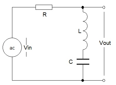

=> when ω is small, Vout/Vin ≈ 1 and
when ω is very large, Vout/Vin ≈ 1
But there is an interesting case when ω2LC = 1
Vout/Vin = 0
Spread sheets can be very useful for modelling circuits like this one.
There are also many sophisticated circuit modelling programs available.
The diagrams below were created with Tina-TI
NOTE both axes have logarithmic scales, with the vertical axis being in Decibels.
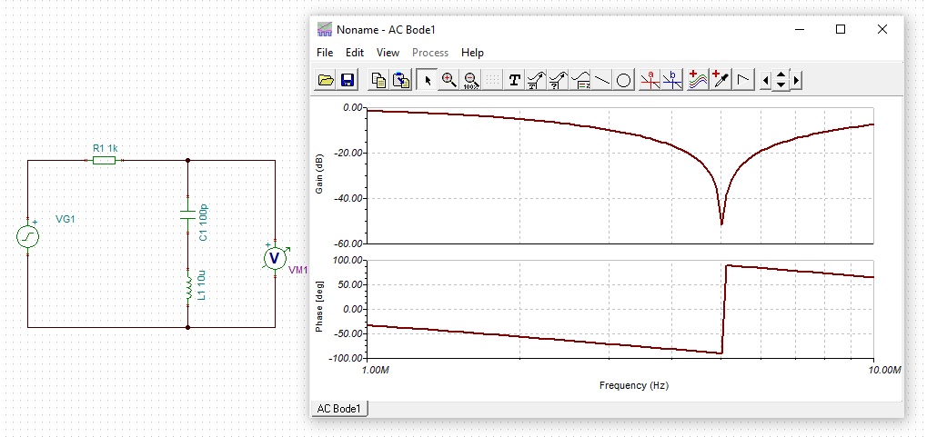
A resistor, capacitor and inductor arranged in series form a series tuned circuit.
Tha series tuned circuit attenuates a particular frequency, determined by when ω2LC = 1
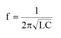
Rearranging this gives the standard frequency formula for a tuned circuit
While circuits that attenuate a particular frequency have many uses, a circuit that selects a frequency is more use.
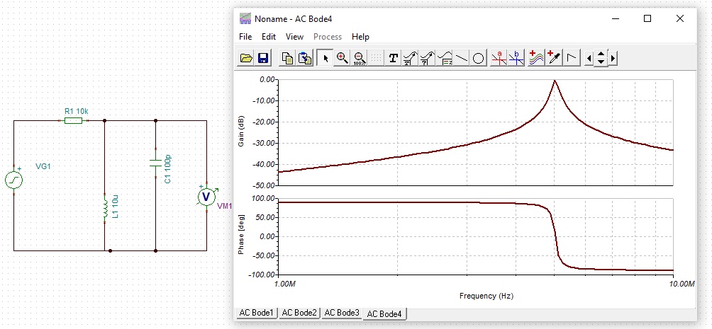
It is also useful to note that the formula for the resonant frequency of a parallel tuned circuit is not quite the same as the formula for a series tuned circuit.
Real circuits need to consider the input and output resistance as well as the resistance of the inductor.
The circuit analysis becomes signficantly more complex and circuit modelling programs become essential.
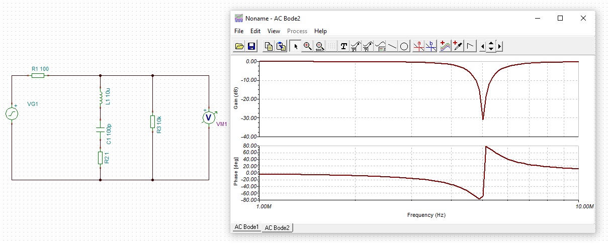
A real series tuned circuit.
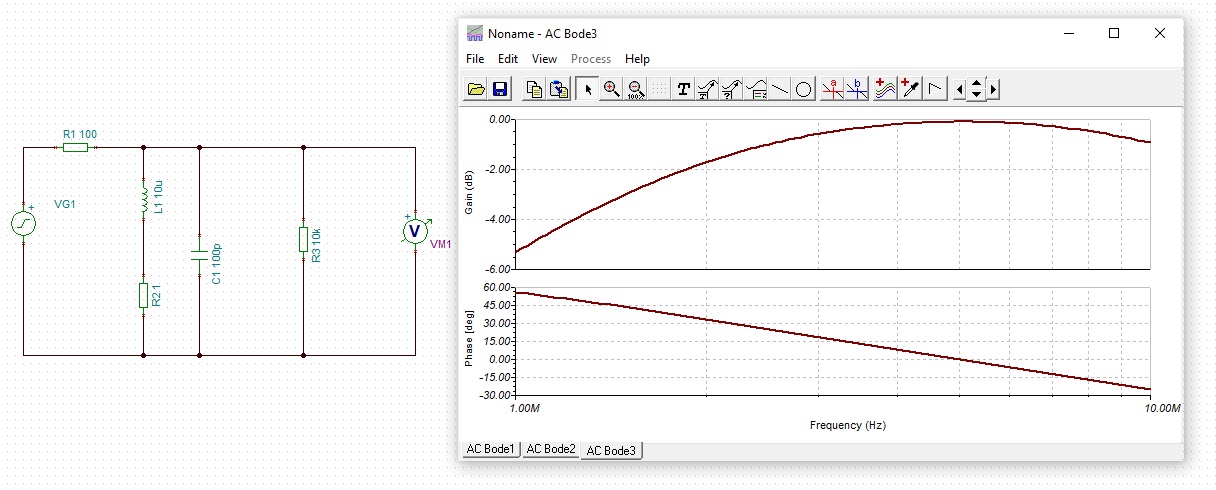
A real parallel tuned circuit with a low resistance source.

A real parallel tuned circuit with a high resistance source.