Inductors in AC circuits
Introduction to the sine wave formula
An alternating current can be represented by
I = I0sin(ωt),
where I0 is the amplitude of the current and ω = 2π×frequencyFor an ideal resistor, using Ohm's Law, the alternating voltage across a resistor, R, is give by
V = R×I0sin(ωt),
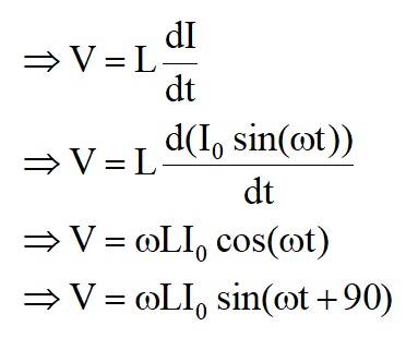
As can be seen from the current and voltage formulae, they are always in phase.For an ideal inductor, the induced voltage across an inductor when a current, I, is passing is given by Faraday's Law
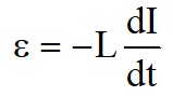
So for an ideal inductor, the applied voltage, V, must be equal and opposite to this induced voltage.
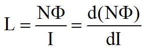
For an ideal inductor, the ratio of the applied voltage to the current passing through is called the reactance, XL.
This should be compared to Ohm's law where the ratio of voltage to current is called resistance.
XL = ωL
As can be seen from the formula, inductive reactance increases linearly with frequency.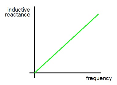
An inductor and resistor in series.
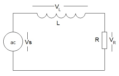
I = I0sin(ωt),
and is the same through both the resistor and inductor as they are in series.=> The voltage across the resistor, R, is
VR = RI0sin(ωt),
and is in phase with the current.=> The voltage across the inductor, L, is
VL = ωLI0sin(ωt + 90),
=> The voltage across the inductor leads the current by 90° (π/2 radians)To make sense of what this means, it is helpful to represent these voltages and currents on a diagram.
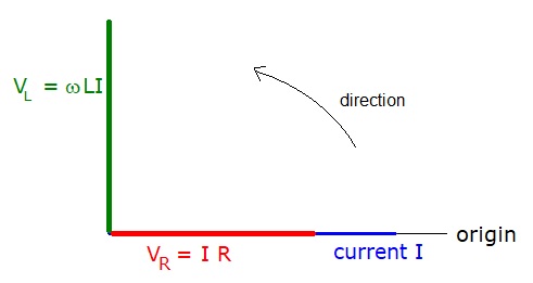
Since VL and VR are not in phase they must be added as vectors.
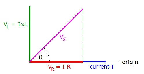

Containing both resistance and reactance, it is called the Impedance of the circuit with the symbol Z.
Z = √(R2 + XL2)
The power supply voltage is out of phase with the current by angle θ, where tanθ = VL/VR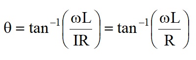
AC Circuits in Complex Form
It is very convenient to use Complex numbers for processing AC calculations.
The real axis represents Resistance. Power is only dissipated in pure (real) resistance.
The imaginary axis represents Reactance. Power is NOT dissipated in reactance (averaged over a time period).
Unfortunately, i is the symbol used to represent current.
To avoid confusion in circuit calculations, j is used to represent √(-1)
Inductive reactance, XL, becomes jωL
RL Potential Divider
The basic resistor Potential Divider formula is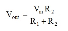
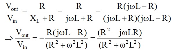
=> when ω is small, Vout/Vin ≈ 1 and
when ω is large, Vout/Vin ≈ 1/ωL
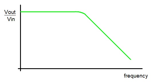
If the inductor and resistor swap places in the circuit above, it is worth verifying that a High Pass filter is formed.