Voltage (Potential) Divider

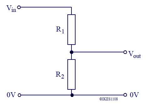
The circuit diagram of a voltage (potential) divider is shown above.
The resistors R1 and R2 are connected in series. The combined resistance is (R1 + R2).
The voltage across these resistors is Vin.
From Ohm's Law, the current, I, passing through the resistors is I = Vin/(R1 + R2)
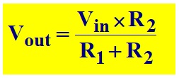
The output voltage, Vout = I × R2 = Vin × R2/(R1 + R2)
The output voltage, Vout, is given by the formula below.

This formula is only valid if there is no current passing from the output of the voltage divider.
In practice, the formula is fairly accurate so long as any current passing from the output is small (<10%) of the current passing through the voltage divider.
The voltage divider circuit is often used to connect resistive sensors (e.g. LDR) to processor inputs.
The resistive sensor replaces one of the resistors in the voltage divider.