Input sub-systems
Electronic systems are only able to process information if the information is first changed into electrical signals
which represent that information.
This is the function of the input device or transducer.
There are two main classes of input devices and subsystems:
• those that have a change of their property (e.g. resistance), e.g. a switch, a thermistor, etc
• those that give out a voltage or current signal, e.g. a dynamic microphone, a photodiode, etc
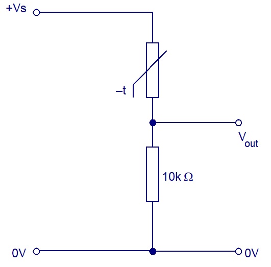
The input devices that have a change of resistance are usually connected to a processor with a voltage (potential) divider circuit.
Resistive sensors
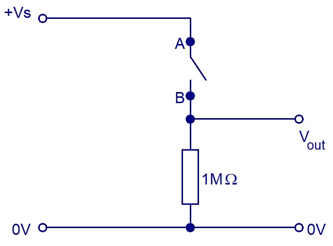
These are an extreme form of sensors whose resistance changes from extremely high to extremely low,
depending on the state of the switch.
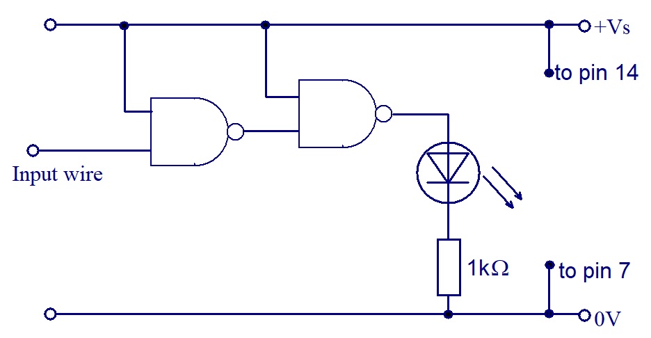
Make up an AND gate circuit, using the 4093 IC, on the protoboard.
Connect the LED and 1kΩ resistor to the output of the AND gate.
Connect a 1MΩ resistor to the Input wire of the AND gate.
Connect a switch between points A and B. Investigate what happens when the switch is operated.
Swap the positions of the 1MΩ resistor and switch.
Investigate what happens now when the switch is operated.
Investigate different types of switch and note the difference between NO and NC contacts.
Investigate making a touch switch, which activates the AND gate when your finger touches points A and B.
How could this be used as a rain, water or moisture sensor?
Design a circuit to turn on a LED when it rains
LDR
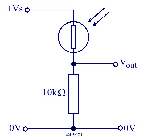
These are sensors whose resistance changes with the amount of light falling onto the sensor.
Using the AND gate circuit, connect a LDR and 10kΩ resistor to the input.
Investigate what happens when the light level changes from light to dark.
Swap the positions of the 10kΩ resistor and LDR.
Investigate what happens when the light level changes from light to dark.
Design a circuit to turn on a LED when it gates dark
Thermistor
These are sensors whose resistance changes with temperature.
Using the AND gate circuit, connect a thermistor and 10kΩ resistor to the input.
Investigate what happens when the temperature changes from cool to warm.
Swap the positions of the 10kΩ resistor and thermistor.
Investigate what happens when the temperature changes from cool to warm.
What is the difference between ntc and ptc thermistors?
Design a circuit to turn on a LED when it gets cold
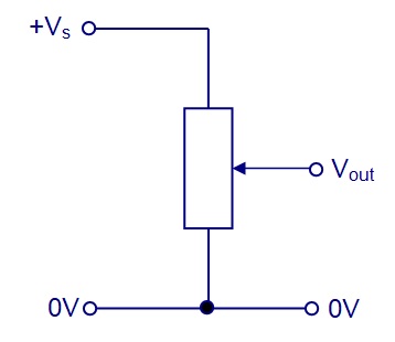
Variable resistors and Potentiometers
These are sensors whose resistance changes with position, either angular or distance.
They can also be used to give a variable voltage.
Using the AND gate circuit, connect a potentiometer across the power supply with the wiper going to the input of the AND gate.
Also connect a voltmeter to the input of the AND gate and 0V.
By adjusting the position of the potentiometer wiper, measure the input voltages to the AND gate for when
- the LED lights and
- when it doesn't.
What do you notice about these two voltages?
The logic gate you are using has 'Schmitt trigger' inputs.
The voltage needed to be logic 1 is different to the voltage needed to be logic 0.
This is known as 'Hysteresis'.
