Introduction
Electricity Fundamentals
To enable circuits/systems to be built quickly, Push-In or Solderless Breadboards have been developed.
These often have many different commercial names and shapes but they all work on the same principle,
that of the wires of the components being pushed through holes in a plastic case and held tightly by a metal spring.
The general name used for all of these boards is PROTOBOARDS.
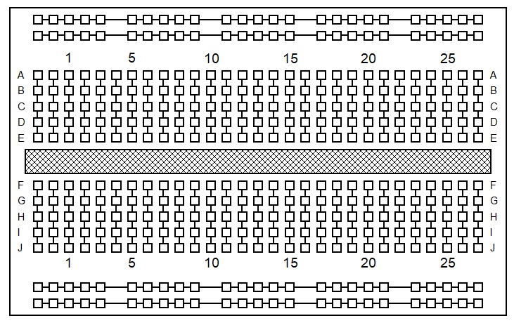
The layout of a typical protoboard is shown in the diagram opposite.
Each hole on the board will accommodate one wire.
The lines show which holes are joined together by the metal springs.
The holes in the main body of the protoboard are joined vertically, with a gap in the middle to accommodate integrated circuits.
The holes at the top and bottom of the board are joined horizontally and can be used as power supply lines.

Circuit diagrams are usually drawn using symbols to represent the different components.
This enables circuit diagrams to be drawn quickly.
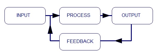
All electronic systems consist of up to four subsystems: INPUT, PROCESSOR, OUTPUT and FEEDBACK.

To start building circuits/systems to investigate different input subsystems, a processor and output subsystems are needed.
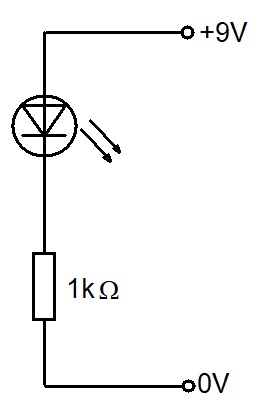
The simplest output subsystem is an LED (Light Emitting Diode).
The current through an LED needs to be limited.
This is usually done by connecting a resistor in series with the LED.
The circuit diagram of the resistor and LED is opposite.
This is assembled on the protoboard as below

Connect the 9V battery and check that the LED lights.
(If it does not, then check that the flat side of the LED faces the resistor.)
Now remove the red wire from the LED and the positive power supply line.
The LED and resistor should be left connected so that they can be used as an output for the next circuits.

The first processor to examine is a NAND gate.
These are usually manufactured as Integrated Circuits (ICs) which contain four or more NAND gates.
An IC consists of a tiny piece of silicon onto which complex circuits are fabricated directly.
Putting circuits into IC form has many advantages, the main one for the user is that very complex circuits
can be constructed quickly by using ICs as building blocks.
The NAND gate IC has a serial number of 4093, and has 14 pins or 'legs'.
For the circuits that follow, the IC should be carefully placed across the centre of your protoboard, as in the diagram opposite.
The power supply should first be connected to the IC.
Connect pin 7 to the 0V power supply line.
Connect pin 14 to the positive power supply (+Vs) line.
Circuit diagrams normally assume that this has been done.
Connect pin 3 to the LED output circuit.
Connect wires to pin 1 and pin 2 and use them to verify the truth table for a NAND gate.
Investigate how can a NAND gate be used as a NOT gate.
Investigate how two NAND gates can be used as an AND gate.
