Digital Electronics Introduction
Digital information (signals) consists of a series of voltage pulses, with a HIGH voltage being represented by a 1 and a LOW voltage being represented by a 0.
Digital circuits consist of logic gates which control the flow of digital information.
A logic gate is a device which has one output and one or more inputs.
The output will either be a logic 1 (high) or a logic 0 (low) depending on the input signals.
Many logic gates have a very high input resistance, and a low output resistance.
Logic 0 is assumed to be less than half of the supply voltage and logic 1 is assumed to be more than half of the supply voltage.
These are the characteristics of the CMOS, 74HC and 74HCT logic families.
All of these logic circuits will operate from a stable +5V supply.
It is assumed in circuit diagrams that a power supply is connected even though it is not be shown.
Analogue electronics uses continuously varying voltages and so it is not possible to produce tables showing the relationship between every possible input and output as the tables would be infinitely long.
Digital electronics, however, having only two states for each input, does not have this problem.
Tables showing the relationship between inputs and output can be readily constructed for digital circuits.
These are known as TRUTH TABLES.
There are three basic logic functions or gates: AND, OR, and NOT.
All digital electronic circuits are built from combinations of these basic gates.
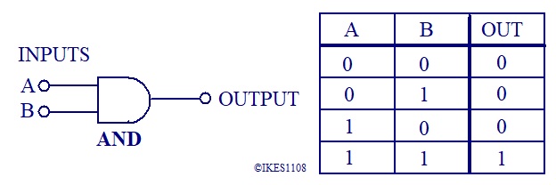
The truth table and logic symbol for a two input AND gate is shown below.

The truth table and logic symbol for a two input OR gate is shown below.

The truth table and logic symbol for a NOT gate is shown below.

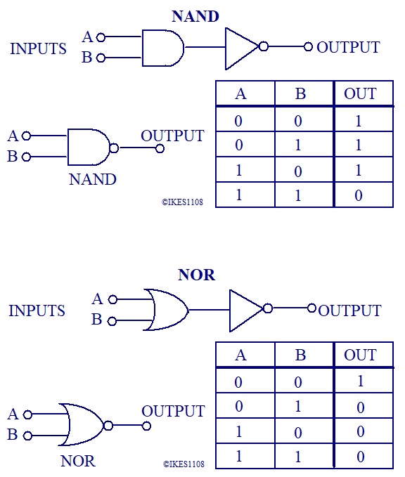
From these basic gates more complex ones can be constructed, the most common of these being the NAND and NOR gates.
The logic symbols and truth tables for these gates are shown below.
