

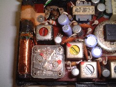
A small medium wave superhet radio.
Note the ferrite rod with tuning coil on the left
and the solid dielectric tuning capacitor at the bottom left.
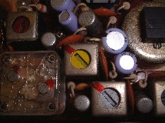
The square metal containers contain the if transformers.
The screws in their tops allows them to be precisely adjusted
to the intermediate frequency.
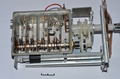
The "front-end" from an old uhf television. (1970s)
Note the four gang tuning capacitor, which adjusts the rf amplifier, local oscillator
and mixer.
The rf amplifier transistor can be seen to the left in the second compartment.
The local oscillator transistor is in the fourth compartment.
The aerial is connected to the top left hand side and the if signal is taken from
the top right hand side.
Note the metal strip inductors.
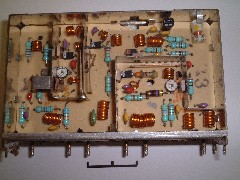
The "front-end" from a more modern uhf television. (1990s)
The rf circuits are tuned by varicap diodes (black squares with silver ends).
This module uses coils as inductors.
The aerial signal enters at the bottom left and leaves at the bottom right .
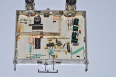
R.F amplifier from a video recorder
Note the input filter, and the protection diodes
on both of the input and output.
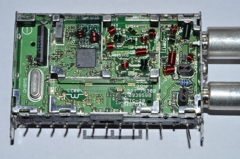
The "front end" for a modern uhf television. (2000s)
Note the phase locked loop and printed circuit inductors.
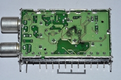
The "front end" for a modern uhf television. (2000s).
Note the copper ground plane and pcb inductors.