
Inductors in DC circuits
Important definitions.
Faraday's Laws of Electromagnetic Induction:
The magnitude of the induced e.m.f., ε, is proportional to the rate of change of 'flux linkage', (NΦ).
Conservation of energy requires that the direction of the induced e.m.f. opposes the change in magnetic flux. (Lenz's Law)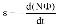
When a current starts to pass through a coil (or single conductor), a magnetic field starts to be created.
This changing magnetic flux creates an induced e.m.f. in the coil. (Faraday's Law)
The direction of this induced e.m.f. opposes the current passing through the coil. (Lenz's Law)
This slows the growth of the current in the coil.
This effect is known as Self Inductance and is given the symbol L.
It is defined by
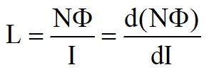
Combining these together gives

(Wb/A) and (V s/A) which is called the henry (H).
Inductor charging.
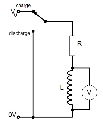
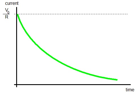
V0 = IR + V
=> V0 = IR - L(dI/dt)

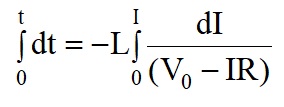
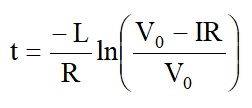

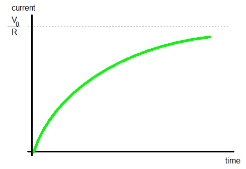
As can be seen from this formula, L/R, has units of time. (Exponents must have no units.)
The quantity L/R is called the Inductive Time Constant.
It is the time taken for the current to increase to ≈ 63% of the final current.
Inductor discharge.
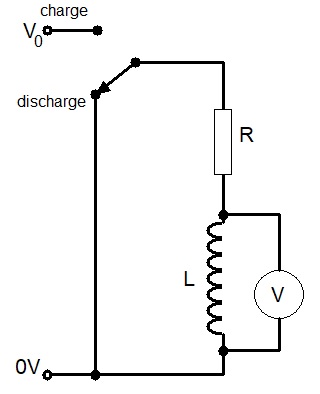
Summing voltages around the loop gives
0 = IR + L(dI/dt)
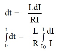

the energy dissipated in the series resistor when the inductor discharges.
Since 0 = IR + L(dI/dt)
=> IR = -L(dI/dt)
Since I2R = -LI(dI/dt) = W
The minus sign represents energy being supplied=> I2R = -LI(dI/dt) = W
Multiplying by time, gives energy, W.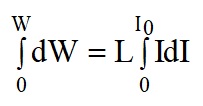
=> W = ½LI02
where I0 = V0/RMany modern electronic power supplies use inductors to increase or decrease the direct voltage from a direct current power supply.
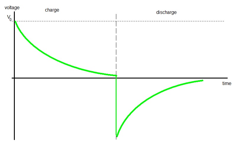
It is interesting to plot the voltage charge/discharge curves for an inductor

Applications
Inductors are used extensively to produce high efficiency direct voltage converters.There are two main types of direct voltage converters:-
- those that reduce the voltage,
- those that increase the voltage.
To reduce the direct voltage a 'buck' converter is used, an outline circuit diagram is shown below.
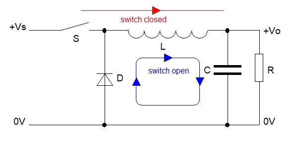
The induced voltage across the inductor opposes Vs, so the voltage across C and R is less than the supply voltage, Vs.
When the voltage across R and C just exceeds the required voltage, the switch opens.
This causes the inductor to produce a voltage in the other direction, which continues to cause a current to pass into R and C.
The diode, D, is now forward biased, allowing the current to circulate.
When the voltage across R and C is just below the required voltage, the switch closes again and the process repeats.
The output voltage is maintained at the required steady value by varying how long the switch is open and closed.
The switch is usually a MOSFET device, and the diode is sometimes replaced with a second MOSFET.
A small amount of power is lost in the MOSFET, diode and resistance of the inductor,
but is significantly less than would be wasted if a series resistor or semiconductor were used.
To increase the direct voltage a 'boost' converter is used, an outline circuit diagram is shown below.
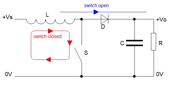
When the switch opens, a voltage is produced across the inductor as the magnetic field collapses.
This voltage across the inductor is in series with the power supply voltage and adds to this voltage.
A current can now flow into the capacitor, C, and the load, R, through the diode, D.
The voltage across C and R will be larger than the supply voltage.
When the voltage across R and C is just below the required voltage, the switch closes again and the process repeats.
The output voltage is maintained at the required steady value by varying how long the switch is open and closed.
The switch is usually a MOSFET device, and the diode is sometimes replaced with a second MOSFET.
Boost regulators are used extensively in battery powered equipment, e.g. mobile phones, where a single LiPo cell (3.6V) is used.
Boost regulators will be used to provide 5V for USB sockets and even higher voltages for the display and transmitter.