Capacitor Revision
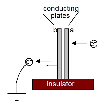
When an electron approaches plate a, an electron is repelled from plate b towards earth.
When an electron is put onto plate a, it will have a negative charge; plate b will have lost an electron to earth and so be left with positive charge.
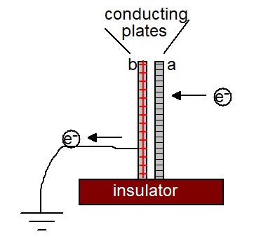
the electrical work done is stored in the electric field between plates a and b.
The electric field strength, E, between the plates;
E = V/d
where V is the difference in electrical potential between the plates and d is the distance between the plates.Capacitance, C is defined as:

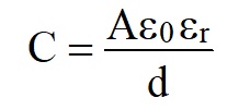
So the capacitance of the two metal plates:


This is valid for the conducting plates.

E.g. If two overlapping metal plates, 10cm by 10cm are separated by 1mm, calculate their capacitance.
C = 0.1×0.1×8.85×10-12/10-3 = 8.85×10⁻¹¹F = 88.5pF
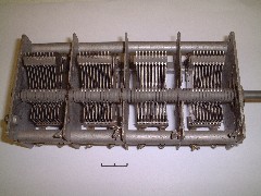
This is an example of a variable capacitor with a maximum capacitance of ≈2000pF
To increase the capacitance, A can be increased and d can be reduced.
Air, at STP breaks down at ≈3000Vmm-1, which limits the maximum potential difference that can be used.
This can be substantially increased by replacing the air between the plates with an insulating material,
e.g, Polystyrene, ≈60,000Vmm-1 and mica, ≈400,000Vmm-1.
Insulators, used in this way are known as dielectrics, and as well as increasing the breakdown voltage, they also increase the capacitance.
The factor by which the capacitance is increased is called the Relative permittivity and given the symbol εr.
For polystyrene is εr≈2 and mica, ≈5
The formula for the capacitance of a parallel plate capacitor with a dielectric becomes
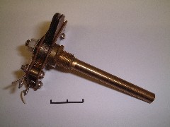
With a dielectric, the size is significantly reduced - this having a maximum value of ≈600pF
Two parallel conducting plates have a very limited capacitance, even with a dielectric separator.
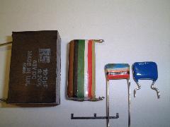
These are fixed value capacitors, with many hundreds of metal plates, separated by a polyester dielectric.
The black one has a value of 10µF (107pF)
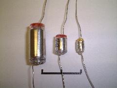
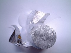
Capacitors can also be rolled up
These capacitors have polystyrene as their dielectric.
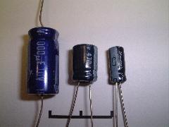
Very large value capacitors can be made by using aluminium oxide as the dielectric, which is chemically formed directly
on the metal plates of the capacitor.
These are known as Electrolytic capacitors and require a very small current to pass through the capacitor
to maintain the aluminium oxide layer.
As a result, they are polarised and have to be connected the correct way round in a circuit.
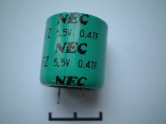
This one has a value of 0.47F, - compare with the earth at 7.1×10⁻⁴F!
Types and uses of capacitors
Super capacitors (Ultra capacitors, Electric Double Layer Capacitors, EDLC) often use a carbon coating
on the conducting plates to massively increase the surface area.
These can have values of 100F+ and are often used in electric cars to store energy from regenerative braking.
They have huge power densities (10kW/kg)
More photographs of different types of capacitors.
Capacitor discharge
The circuit below is used to investigate how the voltage across a capacitor varies with time as it discharges through resistor R.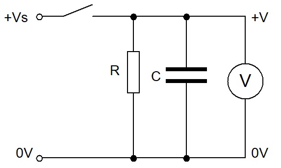
The circuit is set up with the switch closed.
Timing starts when the switch is opened.
Typical results might look like those below.
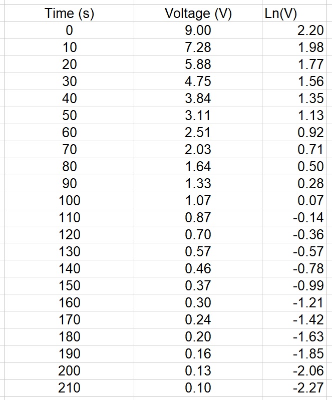
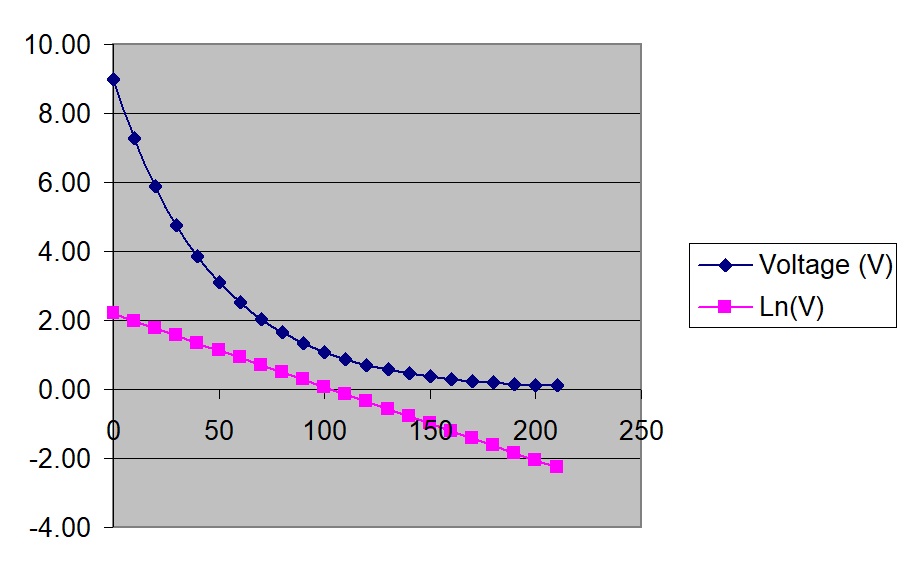
c is the intercept on the 'y' axis and is Ln(Vs), where Vs is the initial voltage across the capacitor
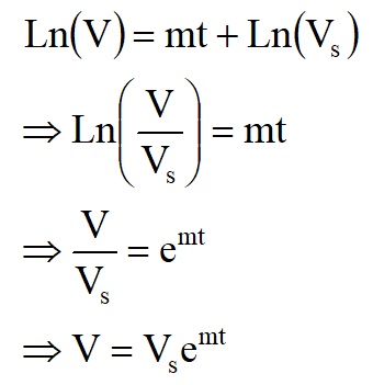

This is an exponential decay curve (compare with radioactive decay curve).
It is worth showing that:-
- the time taken for for the voltage across the capacitor to decrease to ½Vs = 0.693RC
- the time taken for for the voltage across the capacitor to decrease to 37% of Vs = RC
- This time is known as the time constant, T = RC
- The time taken for a capacitor to completely discharge is taken as 5RC, i.e. 5 time constants (0.7% of Vs)
The energy stored in a capacitor can be shown to be
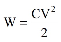
where W is the energy in Joules, C is the capacitance in Farads and V is the potential difference across the capacitor in Volts.
Questions
1). An uncharged 1µF capacitor is charged at a constant current of 0.5µA.(a) Calculate the potential difference (p.d.) across the capacitor after 5s.
(b) Calculate how long it will take for the p.d. to reach 15V.
2). A capacitor is made from two flat sheets of metal, 0.3m × 0.3m, placed 1mm apart in air.
(a) Calculate the capacitance of the arrangement.
(b) Discuss the advantages of replacing the air between the plates with a 1mm thickness sheet of polystyrene.
3). In the circuit diagram below, both capacitors are discharged and both switches are open.
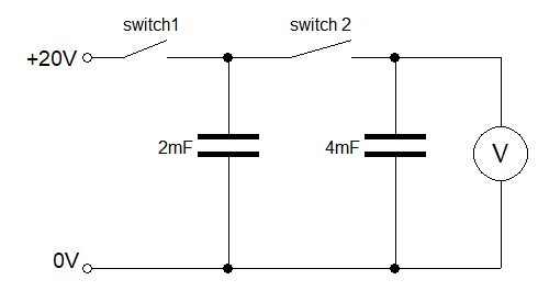
Switch 1 is now closed.
(b) (i) What will be the p.d. across the 2mF capacitor when it has fully charged?
(b) (ii) Calculate the charge stored in the 2mF capacitor when it has fully charged.
Switch 1 is now opened and switch 2 is closed.
(c) Calculate the reading on the voltmeter.
Switch 1 is now closed and switch 2 remains closed.
(d) Calculate the additional charge that flows from the 20V power supply.
4). A 1000µF capacitor is in parallel with a 10kΩ resistor is charged to 12V by a power supply.
(a) Calculate the energy stored in the capacitor.
The power supply is now disconnected.
(b) Calculate the time taken for the potential difference across the capacitor to become 1.5V.
5). An electronic flash gun contains a 470µF capacitor that is charged to 400V.
When the flash gun is triggered, the capacitor completely discharges through the flash tube in 1ms.
Calculate the power of the lamp required to give an equivalent brightness.
6)*. The circuit diagram below shows a simplified power supply.

(a) Calculate the maximum potential difference across the capacitor when the switch is open.
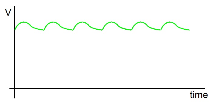
The switch is now closed and the potential difference across the 100Ω resistor, as seen on an oscilloscope, is shown below.
